Wheel Alignment Machine Installation and Bay Preparation Guide
Wheel Alignment Machine Installation and Bay Preparation Guide
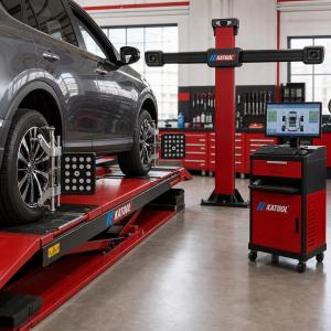
A successful wheel alignment machine installation begins before the equipment arrives. Camera position, platform level, vehicle approach, lighting, electrical supply and calibration space all affect how smoothly the system can be commissioned and used. A technically capable aligner can still produce inconsistent work when it is installed in a bay that blocks camera sightlines or places the vehicle on an unsuitable platform.
This guide helps tire shops, repair centers and equipment distributors prepare an alignment bay. It provides general planning points; the installation drawing and manual for the exact aligner, lift and accessories remain the controlling documents.
1. Match the Aligner to the Lift or Alignment Rack
Start by confirming which platform will support the vehicle. A four-post alignment lift, scissor alignment lift or dedicated rack may use different turnplate recesses, rear slip plates, runway widths and working heights. Confirm that the selected platform supports the intended vehicles and provides the adjustment access required by the workshop.
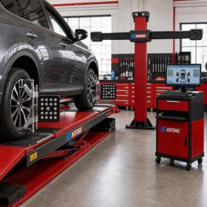
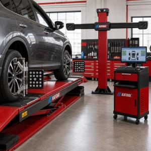
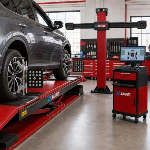
The aligner and lift should be planned as one system. Check where targets or wheel clamps sit at the normal working height and whether cameras can see them throughout the measurement procedure. Shops comparing available lifting equipment can review the Autokato automotive lift range, then confirm compatibility for the chosen combination before ordering.
2. Measure the Complete Alignment Bay
Bay planning should include more than the footprint of the cabinet and rack. Measure vehicle approach length, clear width, ceiling height, camera-to-target distance and technician movement around all four wheels. Include the longest and widest vehicles the shop expects to align, not only a compact demonstration vehicle.
Check doors, columns, tool cabinets, tire machines, hose reels and overhead lighting. A physical obstruction can interfere with target visibility or force technicians into an awkward adjustment position. Mark the proposed equipment locations on the floor and simulate the path of a vehicle entering, stopping and leaving the bay.
3. Verify Platform Level and Mechanical Condition
Wheel alignment measurements depend on a stable reference. The rack or lift should be installed, leveled and inspected according to its own manual before the aligner is calibrated. Verify runway height, turnplate seating, rear slip-plate movement and locking devices. Loose, contaminated or restricted plates can influence the vehicle position during measurement and adjustment.
Do not assume that a concrete floor or lift is level because it looks flat. Use suitable measuring equipment and record the final condition. If the installation uses an existing rack, inspect wear, damage and previous modifications before mounting new alignment equipment.
4. Protect Camera Sightlines
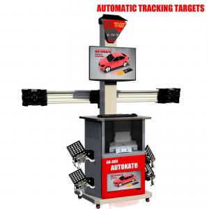
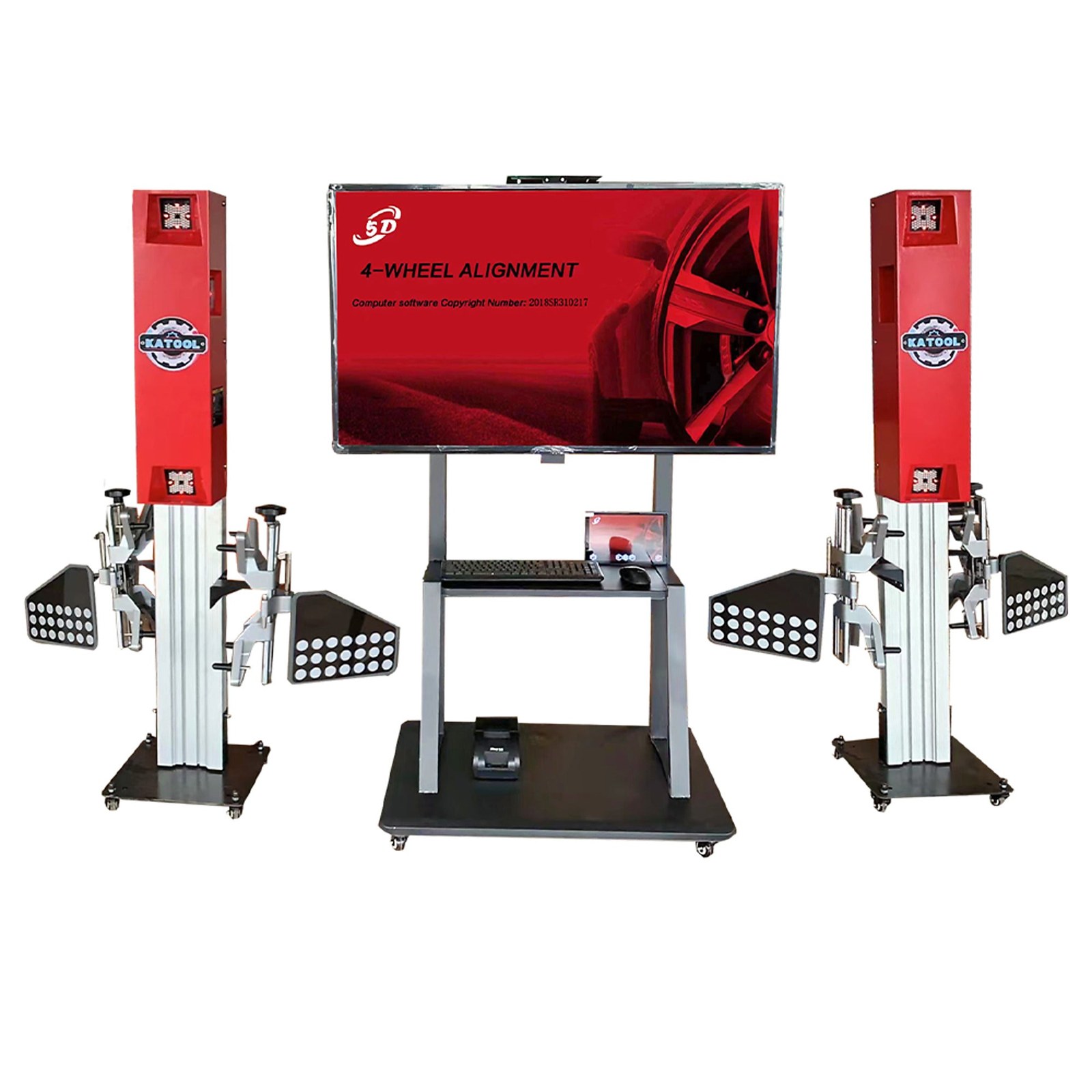
A 3D or 5D wheel alignment system needs a clear view of its targets or reference points. Camera beams, columns or mobile sensor structures must be positioned according to the installation dimensions. Consider the full range of vehicle wheelbases and the target positions used during rolling compensation.
The Autokato KT-5DA 5D wheel alignment machine is one reference configuration for professional alignment bays. Buyers should request the current layout information for the exact ordered version rather than estimating camera distance from product photographs.
5. Plan Power, Computer and Network Connections
Confirm voltage, frequency, outlet type, grounding and circuit protection for the supplied equipment. Position cables so they do not cross vehicle paths, turnplates or technician walkways. Use qualified personnel for permanent electrical work and follow local requirements.
Review computer, printer and network needs before commissioning. Some workshops need customer reports, vehicle database updates or remote technical assistance. A stable connection and an agreed update procedure are easier to arrange during bay preparation than after the machine is in daily use.
6. Control Lighting and Working Conditions
Provide even lighting for target installation, wheel inspection and suspension adjustment, while avoiding direct glare into cameras where the system manual identifies a sensitivity. Keep the equipment within its specified temperature, humidity and environmental limits. Dust, welding activity, water spray and heavy vibration from nearby machinery should be considered when selecting the location.
7. Inspect Clamps, Targets and Turnplates Before Setup
Unpack and identify all wheel clamps, targets, turnplates, steering-wheel holders, brake-pedal depressors, cables and optional accessories. Check for transport damage and confirm that model numbers match the packing list. Contact surfaces should be clean and protective parts should be intact before clamps are installed on customer wheels.
Store targets and clamps where they cannot fall or be struck. A dedicated rack near the alignment bay keeps components organized without placing them in the vehicle approach or camera field.
8. Complete Calibration and Commissioning
Initial setup should follow the exact model procedure. This may include camera alignment, platform compensation, target recognition checks, software configuration and calibration using specified fixtures. Do not substitute a procedure from another aligner simply because the equipment looks similar.
After calibration, use a suitable reference vehicle or verification method to confirm repeatable readings. Mount, measure and if appropriate remount the targets to identify setup inconsistency. Save the commissioning record, software version and calibration date for future troubleshooting.
Technicians can review the four wheel aligner operating guide for a general workflow, while model-specific instructions should come from the Autokato equipment manuals library.
9. Train Operators and Schedule Verification
Operator training should cover vehicle pre-checks, tire pressure, suspension condition, target mounting, rolling compensation, steering procedures, adjustment sequence and report interpretation. Measurement software cannot correct a worn suspension component or a target mounted incorrectly.
Establish routine checks for clamps, targets, cameras, turnplates, cables and computer backups. Recheck calibration or measurement verification after relocation, impact, camera service, platform changes or unexplained repeatability problems. Record corrective action instead of relying on memory.
Wheel Alignment Bay Preparation Checklist
Before delivery, confirm the exact aligner and lift models, installation drawings, vehicle range, bay dimensions, platform level, turnplate and slip-plate condition, camera sightlines, electrical supply, network access, lighting, environmental limits, accessory list, calibration responsibility and operator training plan. Assign each item to the workshop, installer or supplier so responsibilities are clear.
Frequently Asked Questions
Does a wheel alignment machine need a perfectly level rack?
The rack or alignment platform must meet the level and dimensional requirements stated by the aligner and lift manufacturers. Small platform errors can affect measurements, so the completed bay should be checked with suitable instruments before commissioning.
How much space is needed around a 3D wheel aligner?
Required space depends on the camera system, target movement, lift or rack dimensions and the vehicles being serviced. Use the exact installation drawing and measure camera sightlines, vehicle approach, technician access and adjustment positions before ordering.
When should a wheel alignment machine be calibrated?
Follow the model-specific manual for initial setup, calibration and verification intervals. Recheck the system after relocation, camera or target service, platform changes, impacts or unexplained measurement inconsistency.
Conclusion
A dependable wheel alignment bay combines the correct equipment with verified platform geometry, clear camera views, organized utilities and documented commissioning. Autokato Engineering supplies automotive service equipment and supports OEM and ODM projects for distributors, importers and equipment brands. Contact Autokato about wheel alignment equipment with the intended vehicle range, lift or rack model, bay dimensions and destination-market requirements.