
Wheel Balancer Installation Requirements for Workshops
Wheel Balancer Installation Requirements for Workshops
A wheel balancer can only deliver consistent service when the machine is installed in a suitable location. Floor condition, electrical supply, working clearance, lighting and vibration control all influence daily operation. Shops often focus on balancing modes and wheel capacity when comparing equipment, but installation planning is just as important. A poorly positioned machine can slow technicians, expose cables to damage and make repeatable measurements more difficult.
This guide explains practical wheel balancer installation requirements for tire shops, repair workshops and dealership service bays. Always use the installation instructions and electrical data supplied with the exact machine, because specifications can vary by model and destination market.
Choose a Stable and Level Floor Area
Place the balancer on a firm floor that can support the machine and the wheels it will service. The surface should be level, clean and free from movement. An uneven or unstable base may allow the cabinet to rock during operation and can make it harder to obtain repeatable results. Before positioning the machine, inspect the floor for loose coatings, cracks, raised joints or contamination that could prevent stable contact.
Do not rely only on appearance. Check the proposed location with appropriate measuring tools and follow any leveling or anchoring procedure stated in the manual. If the model uses adjustable feet, set them correctly and confirm that the machine remains stable after installation. Buyers reviewing professional options can compare the Autokato wheel balancer range before requesting the installation data for a selected model.
Keep the Machine Away from Unwanted Vibration
A wheel balancer measures small differences in rotating mass, so its location should be separated from avoidable vibration. Heavy presses, vehicle lifts, compressors and other machines can transmit movement through the floor, especially when several pieces of equipment share the same work area. Frequent vehicle traffic or impacts near the cabinet may also disturb service work.
Plan the bay so the balancer has a stable operating zone. It does not need to be isolated from the entire workshop, but technicians should not have to balance a wheel beside equipment that creates repeated shock or strong vibration. If measurement repeatability changes after another machine starts operating, check the environment as part of the diagnosis.
Confirm Voltage, Frequency and Grounding
Read the machine nameplate and order confirmation before preparing the outlet. Voltage, frequency, phase, plug type and circuit requirements must match the supplied configuration. A qualified electrician should complete fixed wiring and verify protective grounding according to local regulations. Extension cords and shared outlets can introduce voltage drop or create a trip hazard, so a properly positioned supply is preferable.
The electrical plan should also consider nearby tire changing equipment, air compressors and chargers. Workshops comparing different supplies can review the single phase vs three phase garage equipment guide. The final decision must still follow the exact nameplate and manual for each machine.
Provide Safe Working Clearance
Technicians need enough room to mount wheels, operate the control panel and move around the machine without striking walls, cabinets or other equipment. Include the full travel of the protective hood when planning clearance. The shaft area must remain accessible for cones, quick nuts, adapters and wheel handling. Leave a clear path for bringing wheels from the tire changer to the balancer.
A practical tire service bay reduces unnecessary lifting and crossing traffic. Position wheel weights, pliers, cones and commonly used adapters within easy reach, but do not place loose tools on the balancer cabinet where they can fall or interfere with operation. The tire changer and wheel balancer workstation layout guide provides additional planning points for a complete service area.
Plan Lighting and Screen Visibility
Good lighting helps technicians inspect the rim, identify old wheel weights and enter dimensions correctly. Avoid placing the display where strong reflections make information difficult to read. The machine should also be protected from direct water spray, excessive dust, welding debris and other conditions outside the limits stated by the manufacturer.
Keep ventilation openings clear. Do not push the cabinet against a wall if doing so blocks airflow, access panels or cable routing. A clean and organized location makes routine inspection easier and reduces the chance that debris collects around moving or electrical components.
Inspect the Machine After Unpacking
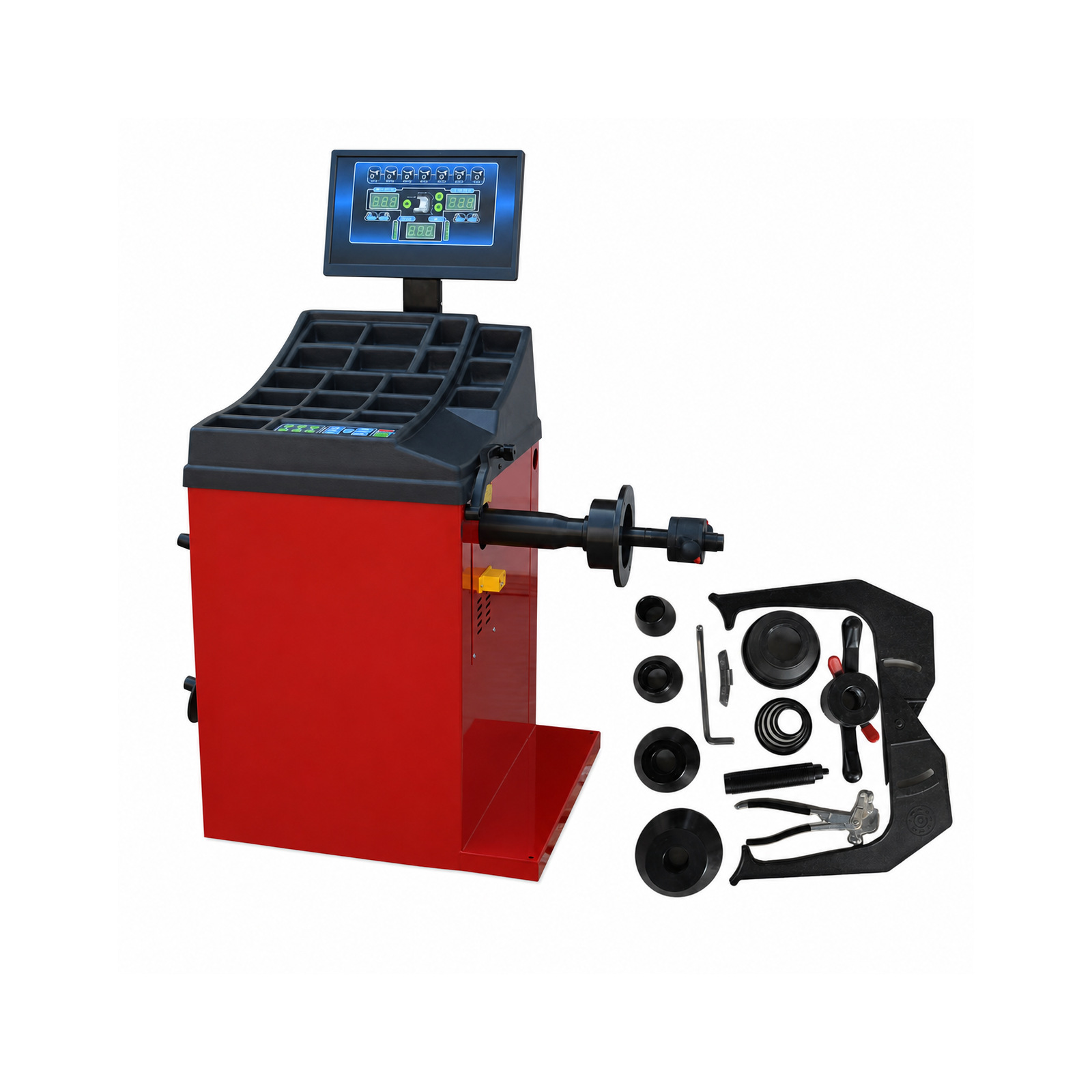
Before assembly, compare the machine, accessories and packing list. Check the shaft, hood, display, cabinet and cables for visible transport damage. Confirm that cones, spacers, quick nuts and calibration accessories match the ordered configuration. Report damage before operating the balancer rather than trying to correct a bent or misaligned component through calibration.
The Autokato KT-B760 wheel balancer and the Autokato KT-B750 wheel balancer machine illustrate two configurations that workshops may compare. Buyers should request the current accessory list and installation information for the exact ordered version.
Complete Initial Setup and Calibration
Assemble the hood, shaft accessories and display components according to the model manual. Confirm that fasteners are secure and cables are routed away from moving parts. Enter any required machine settings before performing calibration. Use the specified calibration wheel, weight and procedure; a routine borrowed from another model may not be suitable.
After calibration, test repeatability by mounting a suitable wheel, measuring it more than once and checking whether the indicated result remains consistent. If readings vary, inspect wheel mounting, cone selection, contact surfaces, shaft condition and environmental vibration before assuming that software adjustment is needed. The wheel balancer calibration guide explains these checks in more detail.
Prepare Operators for Daily Use
Installation is not complete until operators understand correct wheel mounting, dimension entry, balancing modes, weight placement and safety procedures. Keep cones and adapters clean, remove dirt from wheel contact surfaces and inspect the shaft before daily work. Incorrect mounting is a common cause of inconsistent readings even when the machine itself is functioning normally.
Store the model manual where technicians can find it. Autokato also maintains an automotive equipment manuals library for available technical documents. Confirm the exact model number before using any downloaded instructions.
Wheel Balancer Installation Checklist
Before commissioning, confirm the floor is stable and level, the cabinet does not rock, environmental vibration is controlled, electrical supply matches the nameplate, grounding is verified, cables are protected, hood clearance is available, accessories are complete, ventilation remains open and the calibration procedure has been completed. Record the installation date and initial verification result for future maintenance.
Conclusion
A reliable wheel balancing station begins with careful placement and documented setup. Stable flooring, correct power, practical clearance and proper calibration support efficient workflow and repeatable service. Distributors and workshop planners should confirm installation requirements before shipment so the correct machine configuration, accessories and site preparation can be arranged together.